Electronics Production and CNC

How to Make PCBs On a Desktop CNC Mill
The workflow of designing and milling a PCB has four parts;
STEP 1: The first step of the workflow is CAD (computer-aided design), in which the designer uses software to create the circuit schematic and board layout. There are many software packages at many price levels for designing PCBs.We’re very fond of the free version of ‘EAGLE’.

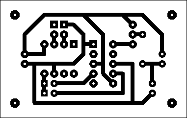
A board layout in EAGLE
EAGLE contains a schematic editor, for designing circuit diagrams. Parts can be placed on many sheets and connected together through ports. The PCB layout editor allows back annotation to the schematic and auto-routing to automatically connect traces based on the connections defined in the schematic. EAGLE saves Gerber and PostScript layout files and Excellon and Sieb & Meyer drill files. These standard files are accepted by many PCB fabrication companies.
STEP 2: The second step in the workflow is CAM (computer-aided manufacturing), in which the designer uses software to generate instructions for the CNC machine based on the board layout. EAGLE has a plugin called pcb-gcode that will translate the board layout to G-code, which is the language of CNC machines. Most other PCB CAD software does not have such a plugin, so there’s an intermediate step of generating Gerber and Drill files. Gerber files are vector images that represent the board layout as coordinates and include other identifying information. Gerber is the standard format used within the PCB industry. Drill files, which usually use the Excellon format, are also commonly used. All PCB software should have instructions for how to generate Gerber and Drill files._
circuit CAM layout.
STEP 3: _The third step in the workflow is milling the board with a CNC machine using the instructions (G-code files) generated by the CAM software. This is where it can get a little confusing because there are many different CNC machines and CNC control software packages to choose from. For control software, Mach3 has a large following and runs on Windows. LinuxCNC is free, also has a large following, and runs on Linux. Both of these programs can run a variety of CNC machines.
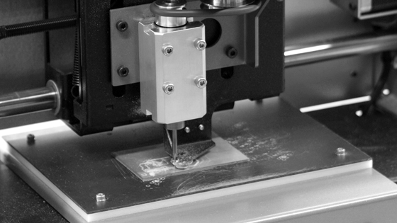
There are many CNC machines to choose from, with a variety of pricing and feature options. Low-cost CNC mill kits are available, but these require hands-on assembly and maintenance, and they don’t have the same precision or ease-of-use as assembled machines. Ultra-high-end PCB mills are available with all sorts of bells and whistles — like vacuum tables, dust collectors, and through-hole plating — but they also have price tags that are often in the tens of thousands of dollars. We think the Othermill, our portable, fully assembled CNC mill, provides a great combination of precision and affordability. It also comes with really good software that’s easy for students and others who are new to milling to learn quickly.
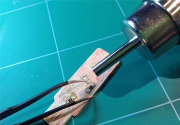
STEP 4: Soldering a PCB
Clean the tip
When the iron hot, start with cleaning the tip to remove old solder from it. You can use a wet sponge, a copper scouring pad or something similar.
Tinning the tip
Before you start soldering, you should tin the tip of the soldering iron. This makes the tip transfer heat faster and thereby making the soldering easier and faster. If you get any droplets of tin on your tip, use a sponge, a copper scouring pad or just shake it off.
Soldering two wires
Start with tinning the two wires. It is useful to have something to hold one wire for you. Place the tip of the iron on the wire and let it heat for a second or three. Then add some solder until the wire is soaked with solder. If it is a thick wire, you should turn up the heat on your iron (if possible) to make the wire heat up faster. Repeat the tinning process on the other wire. Now place the two tinned wires together and hold still while heating them with the soldering iron so that the tin on both of the wires melt together.
Soldering on PBC hole
Put the tip of the iron on the pad so that it heats both the lead of the part and the pad of the circuit board. Heat them for a second or so before you apply solder. Remove the iron and the solder wire and inspect your solder joint to see if it looks okay.